Materials
| Name | Picture |
|---|---|
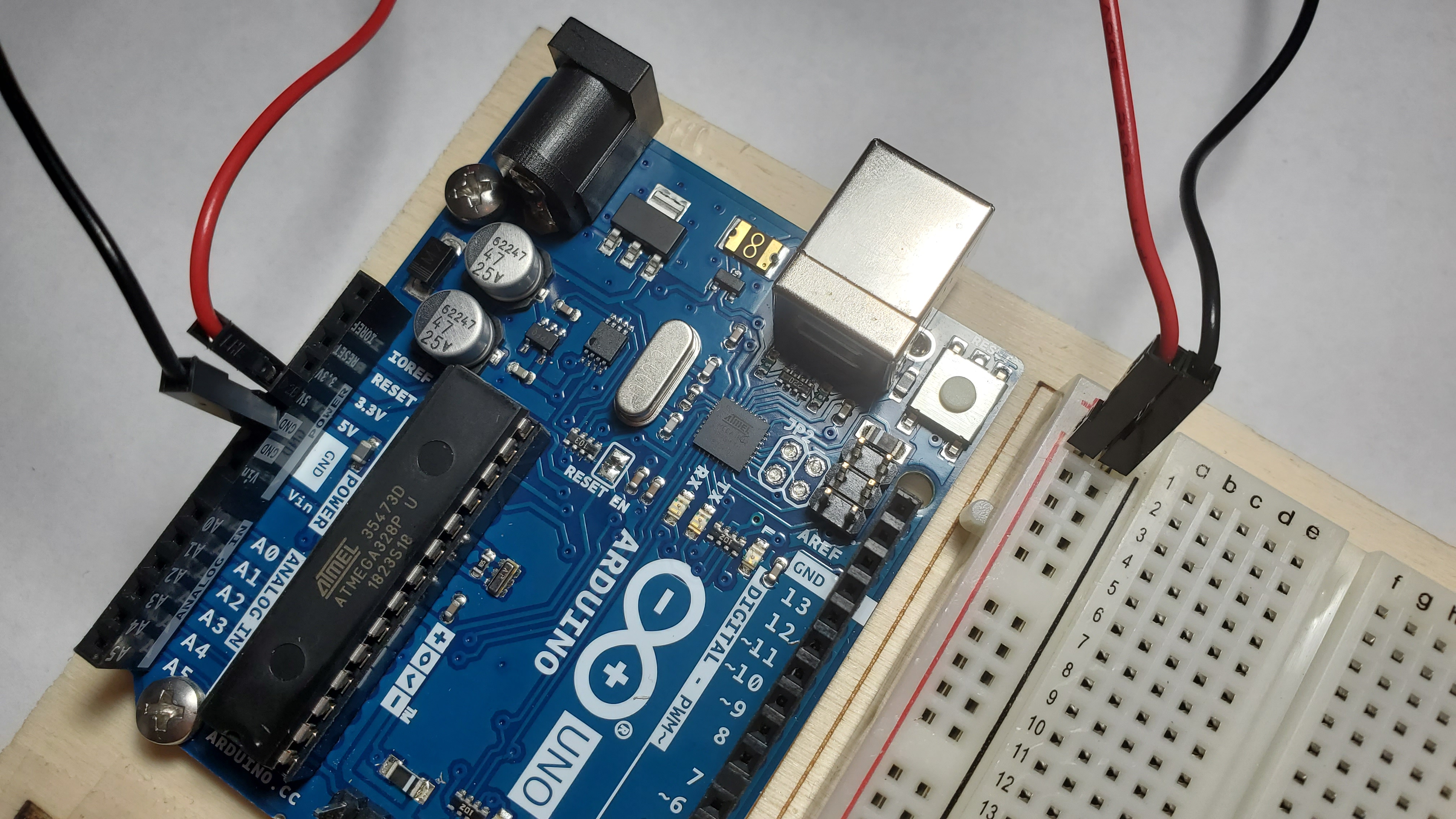
| One Arduino board with breadboard | 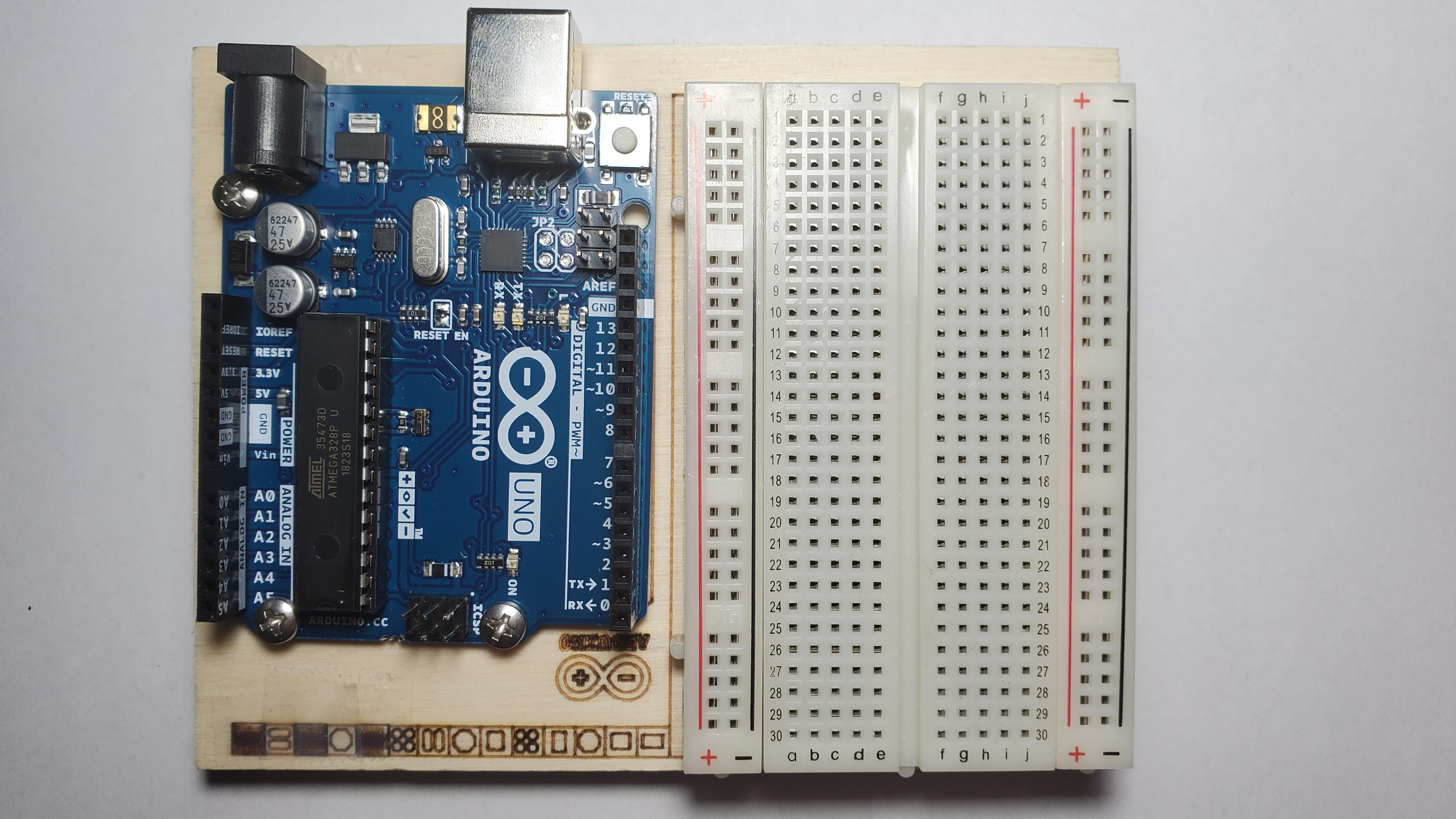 |
| One Black and Red Wire | 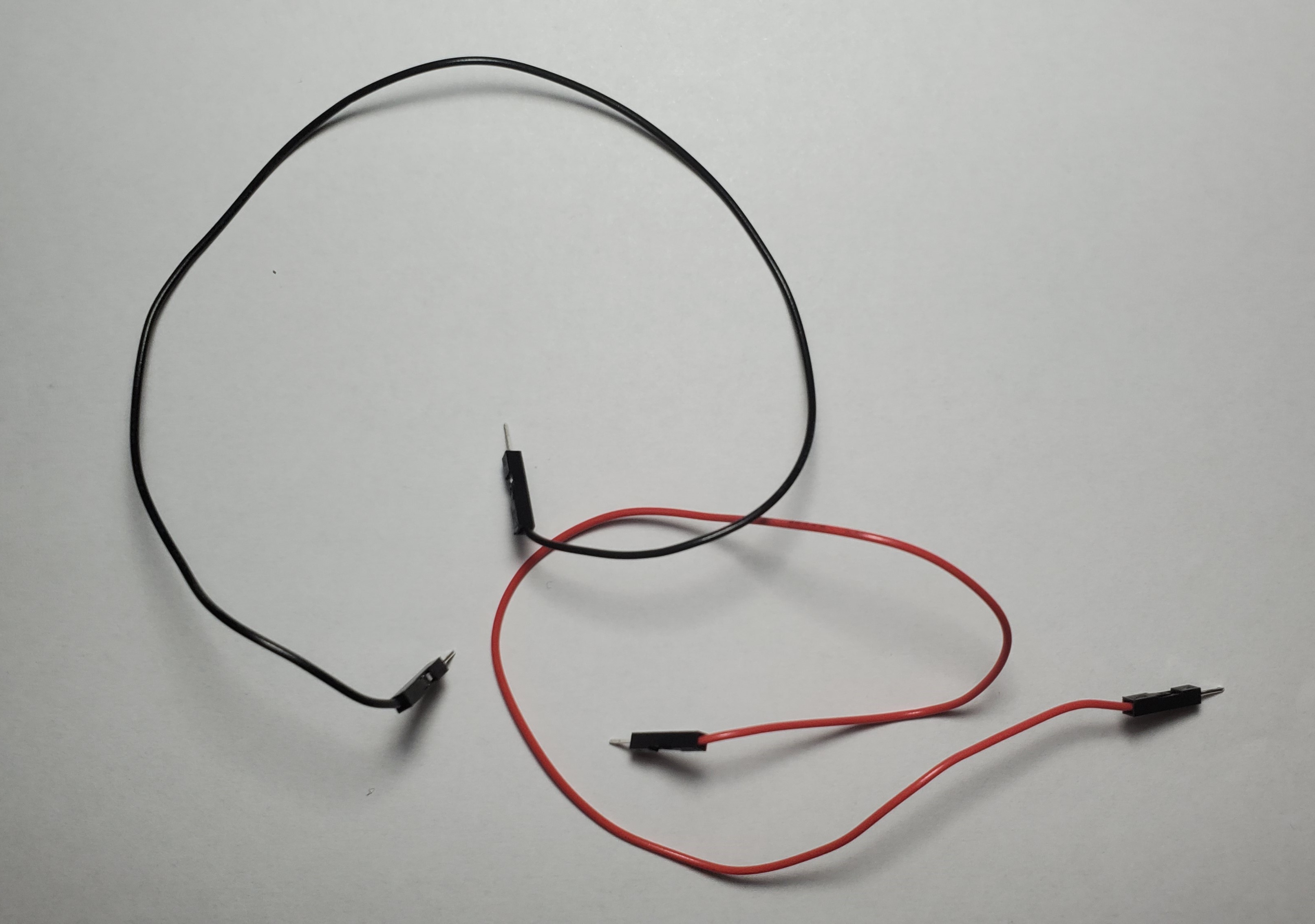 |
| One Green,three yellow wires, and two orange wires | |
| Three 200 ohms Resistor | 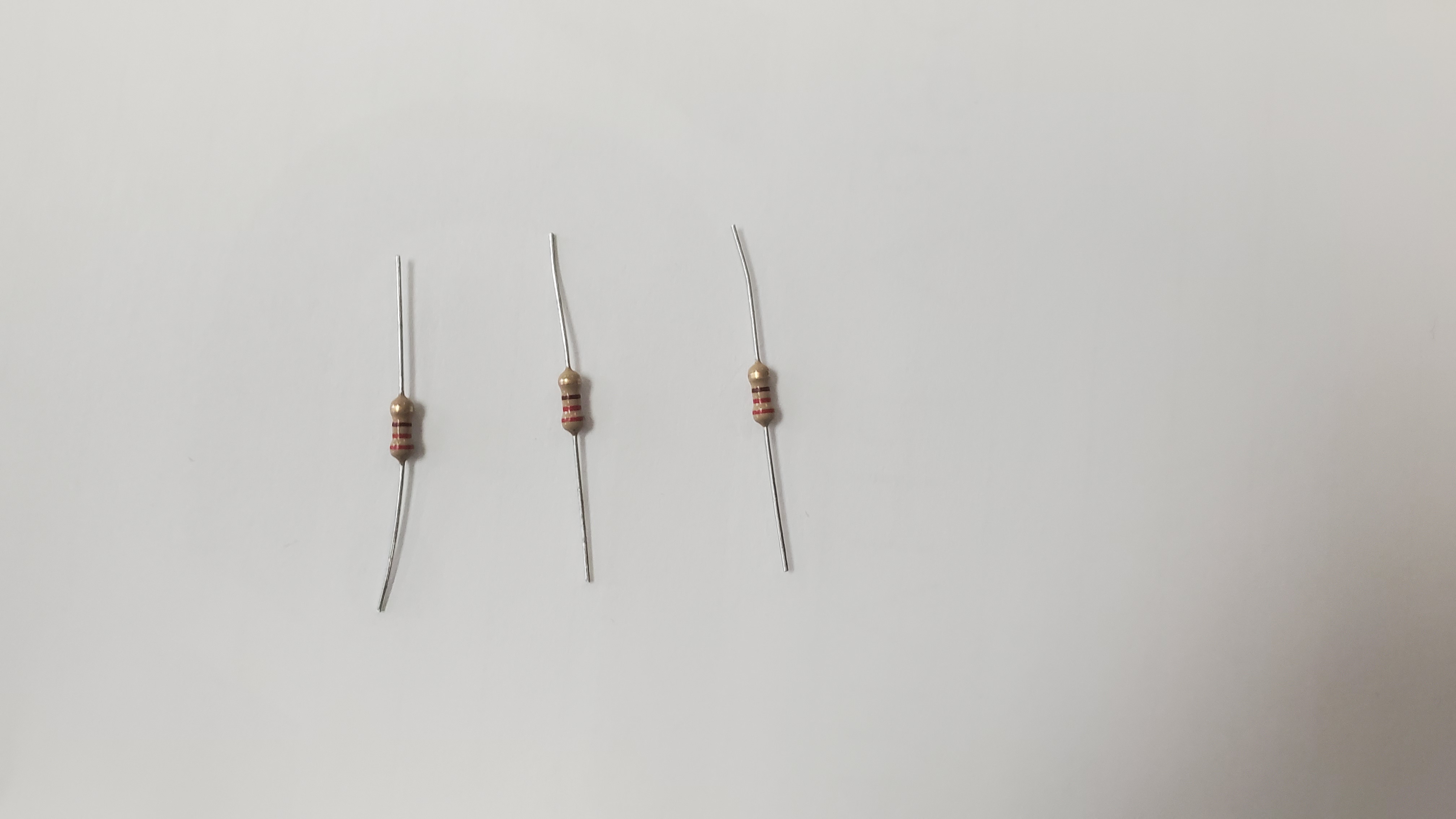 RED- RED-BROWN-GOLD
 |
| Three red LED | 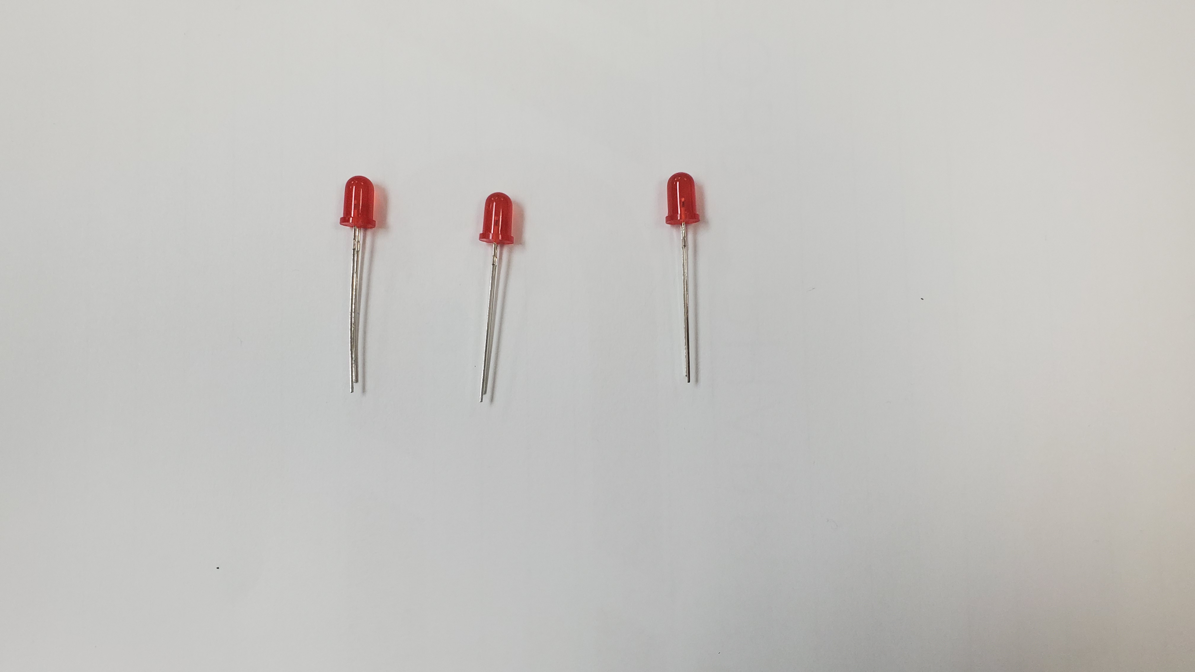 |
| 1 temperature sensor |  |
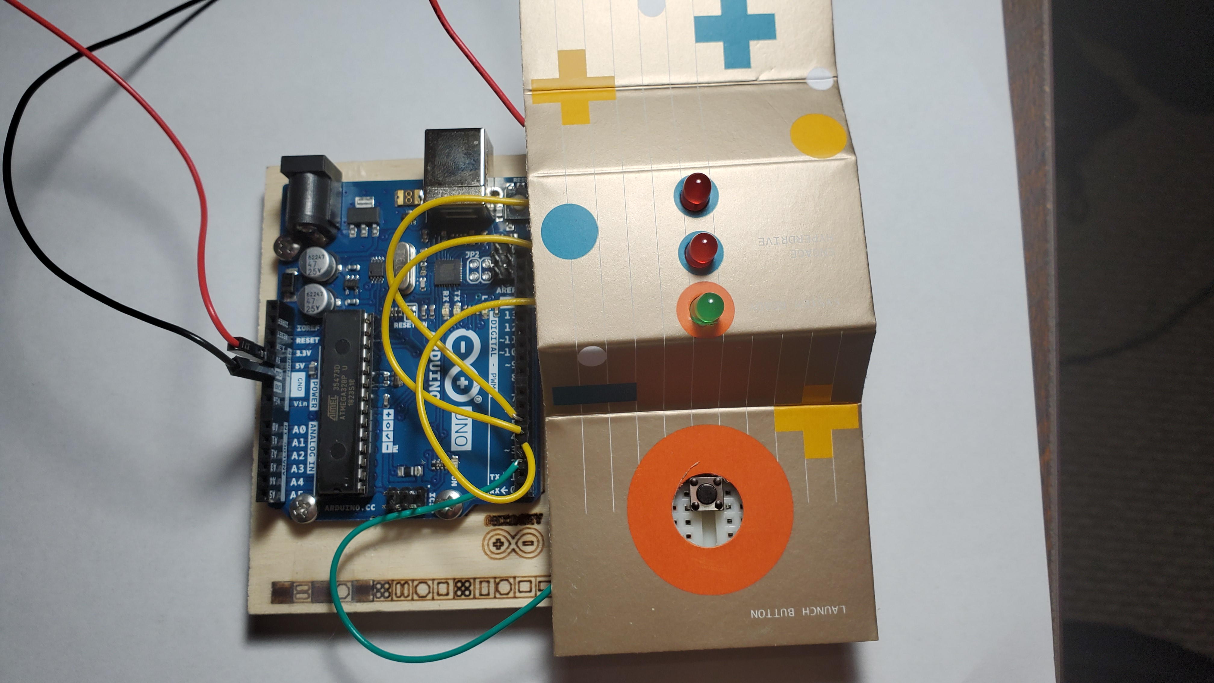
Building Instructions
1) Pin the red and black wire
Pin the red wire from the 5V hole to the red line on the breadboard and Pin the black wire from GND to the black line on the breadboard
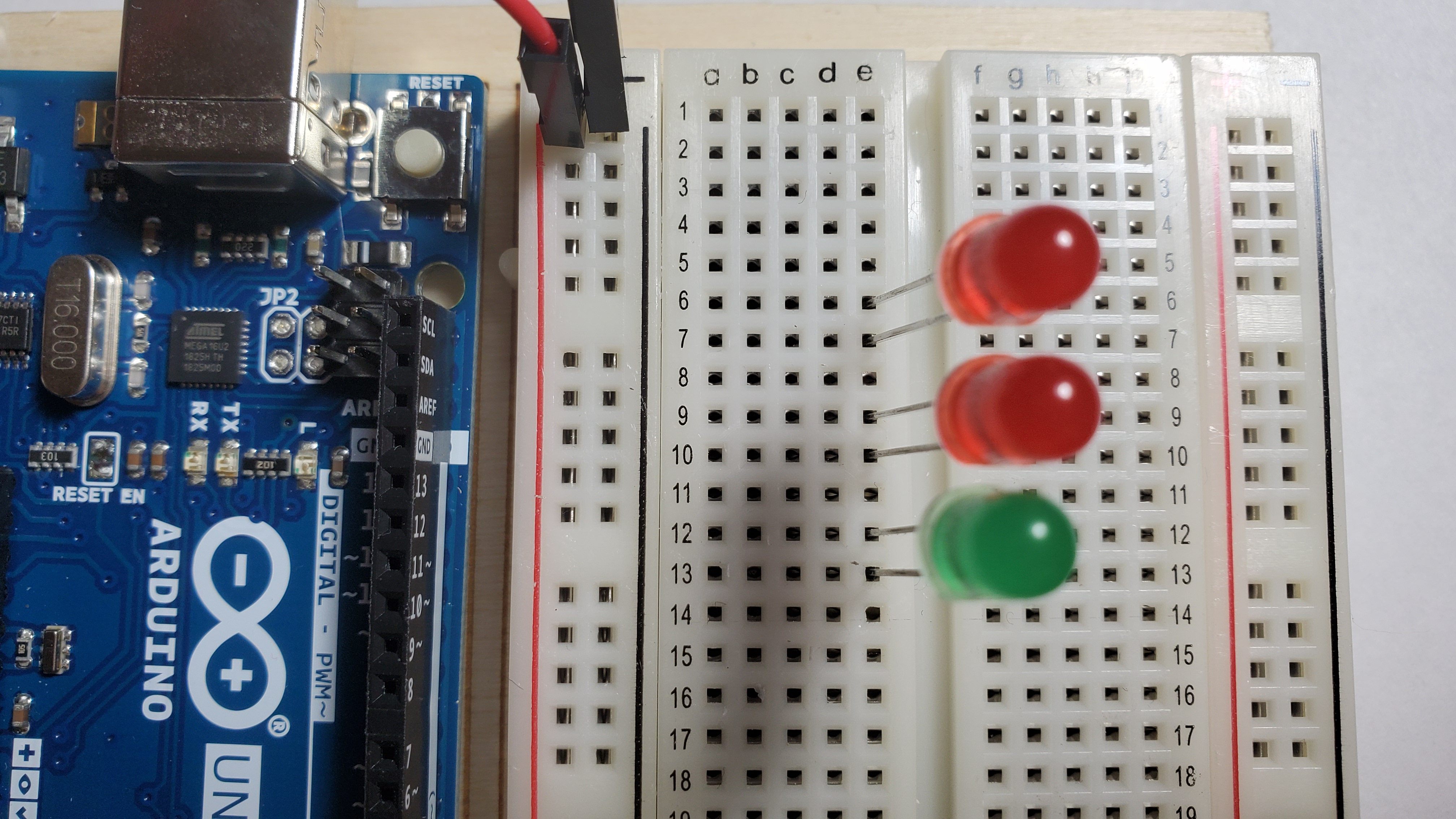
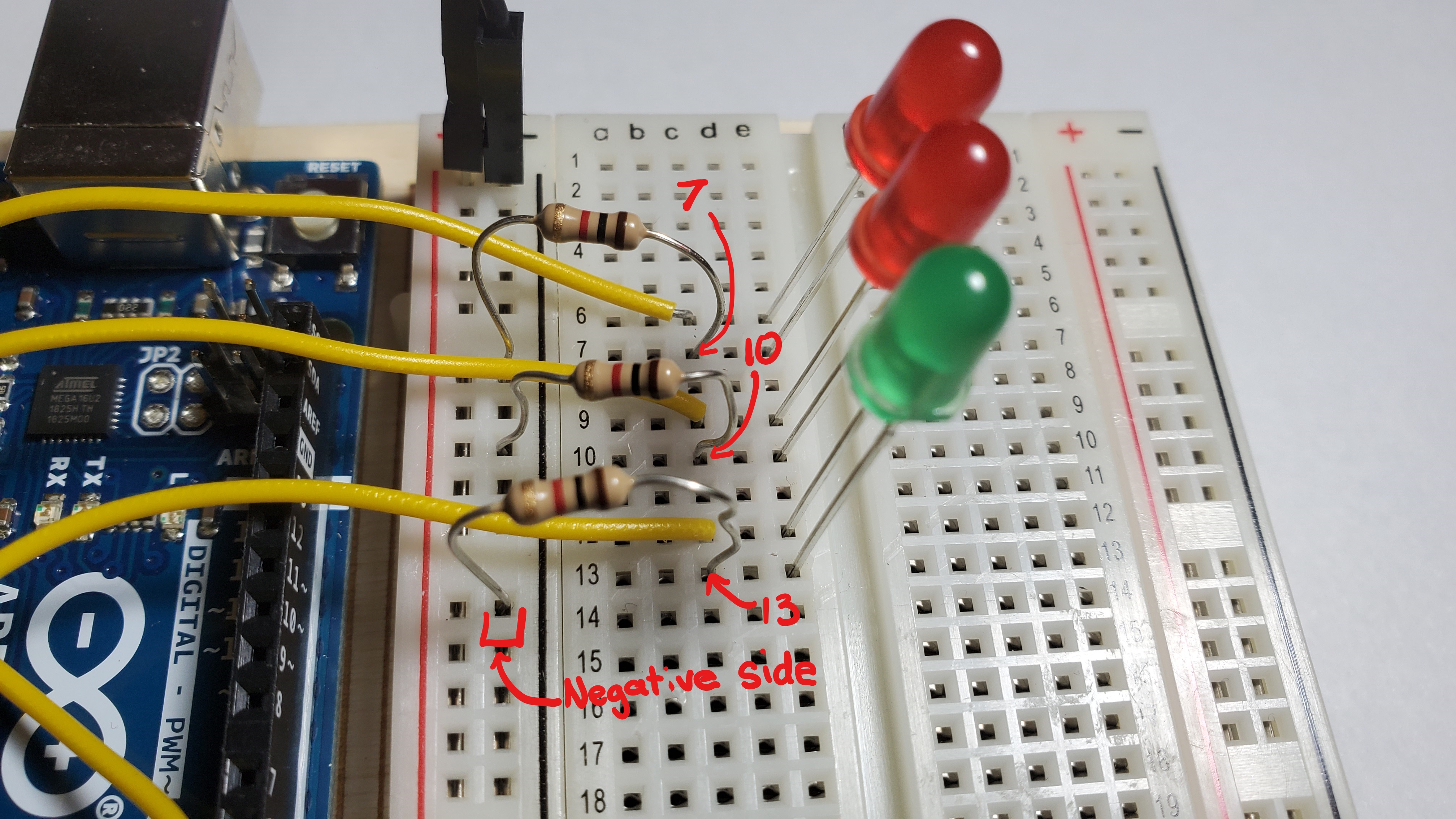
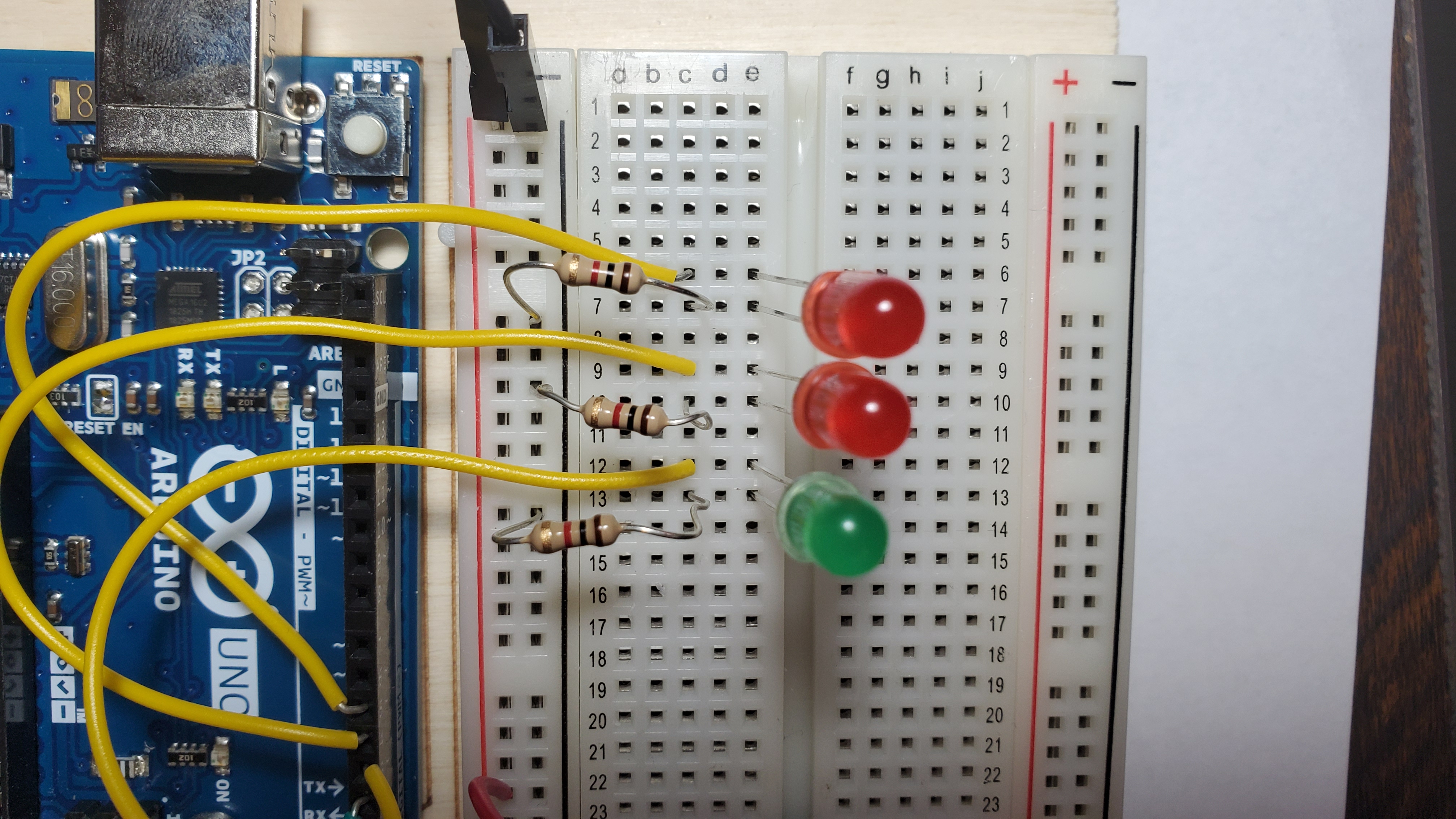
2) Pin the three LEDs
Pin the short leg of a green LED on row 13 column e
Pin the short leg of a red LED on row 10 column e
Pin the short leg of a red LED on row 7 column e
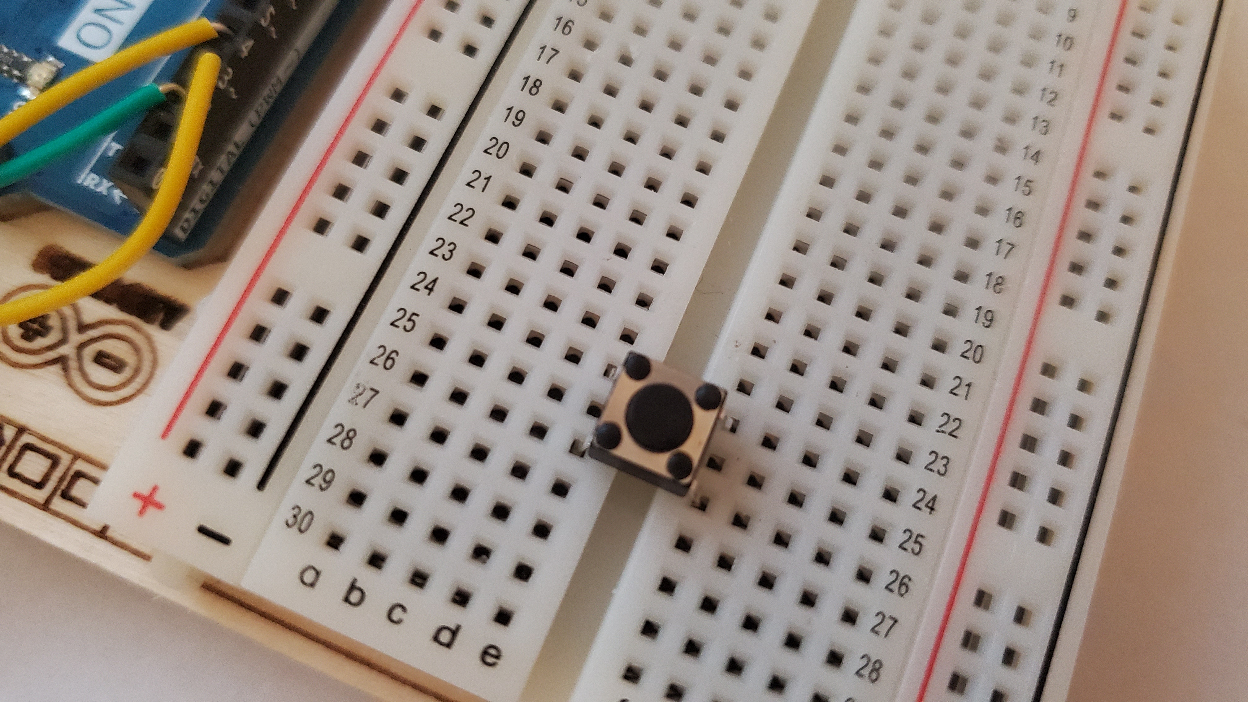
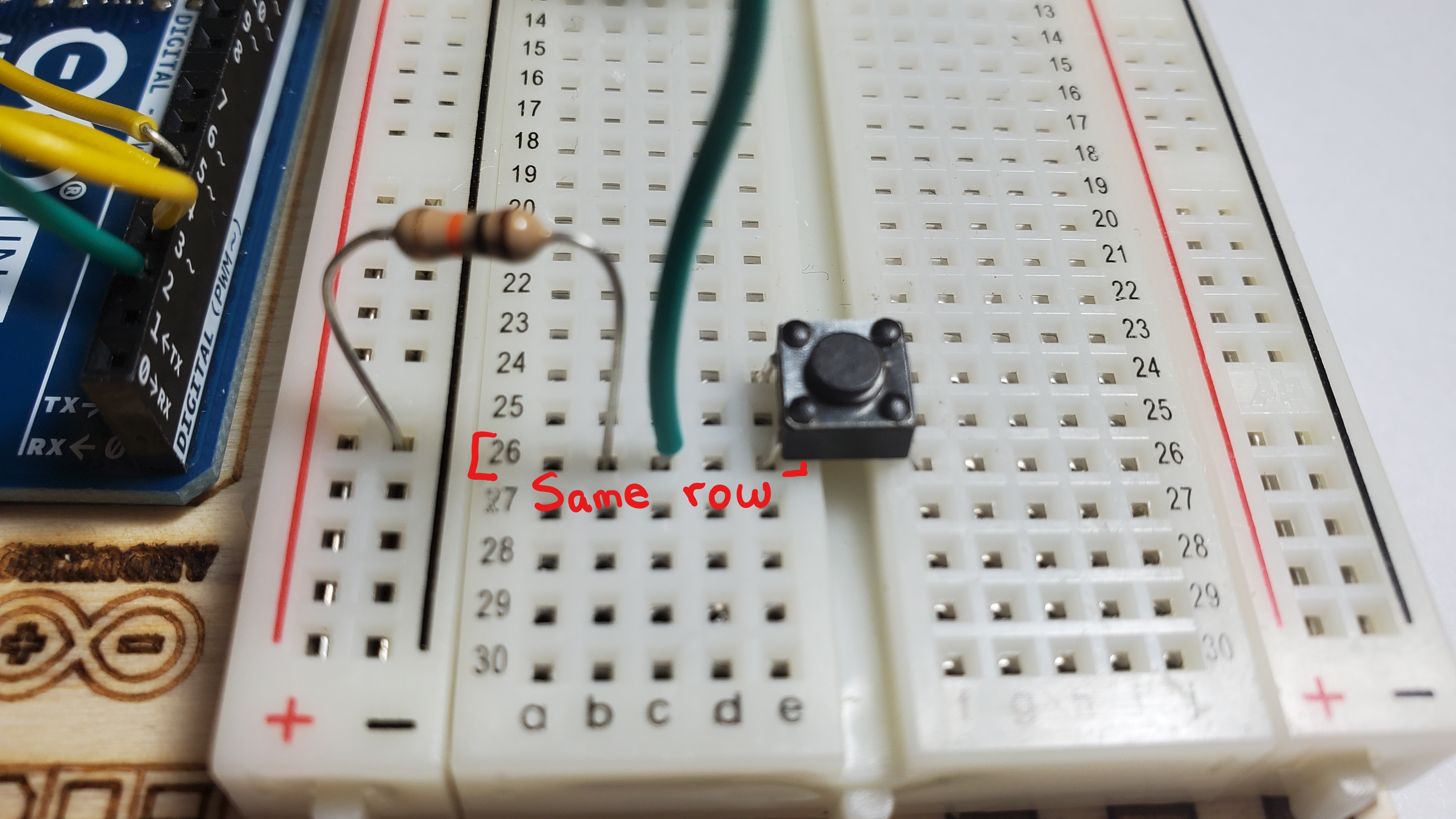
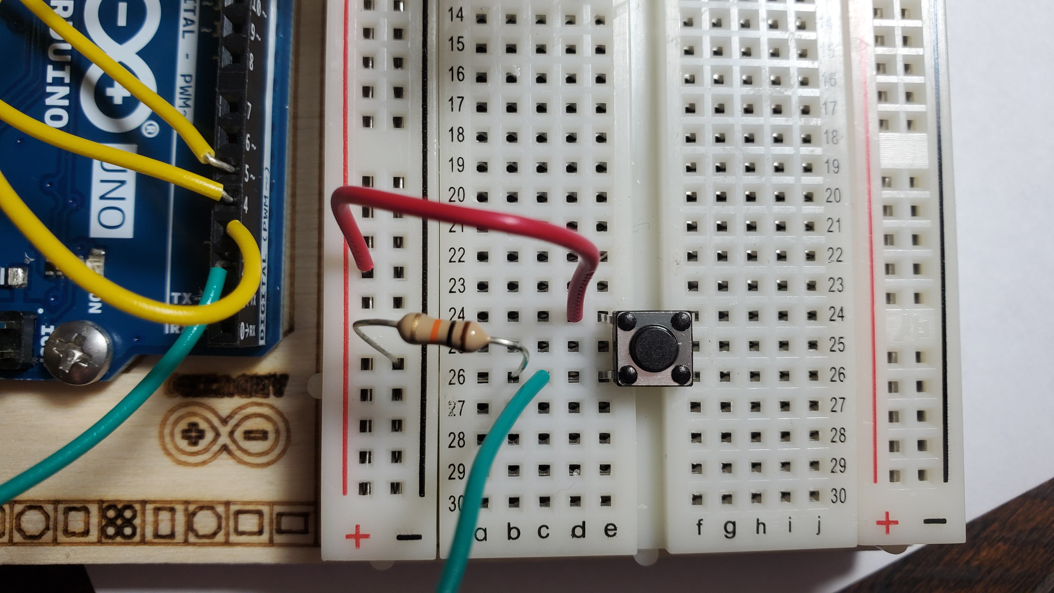
3) Pin the button
Pin the button on row 26
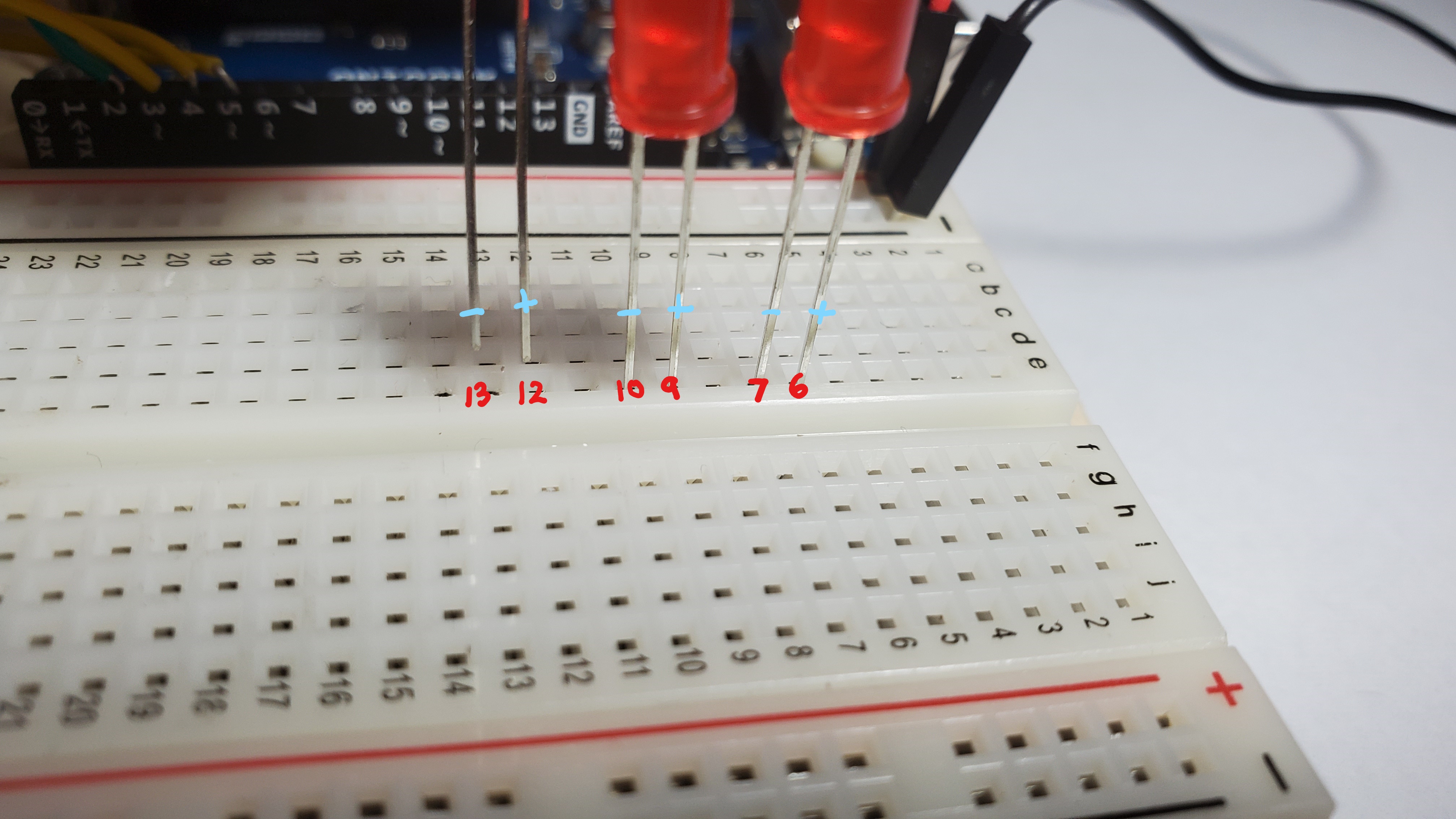
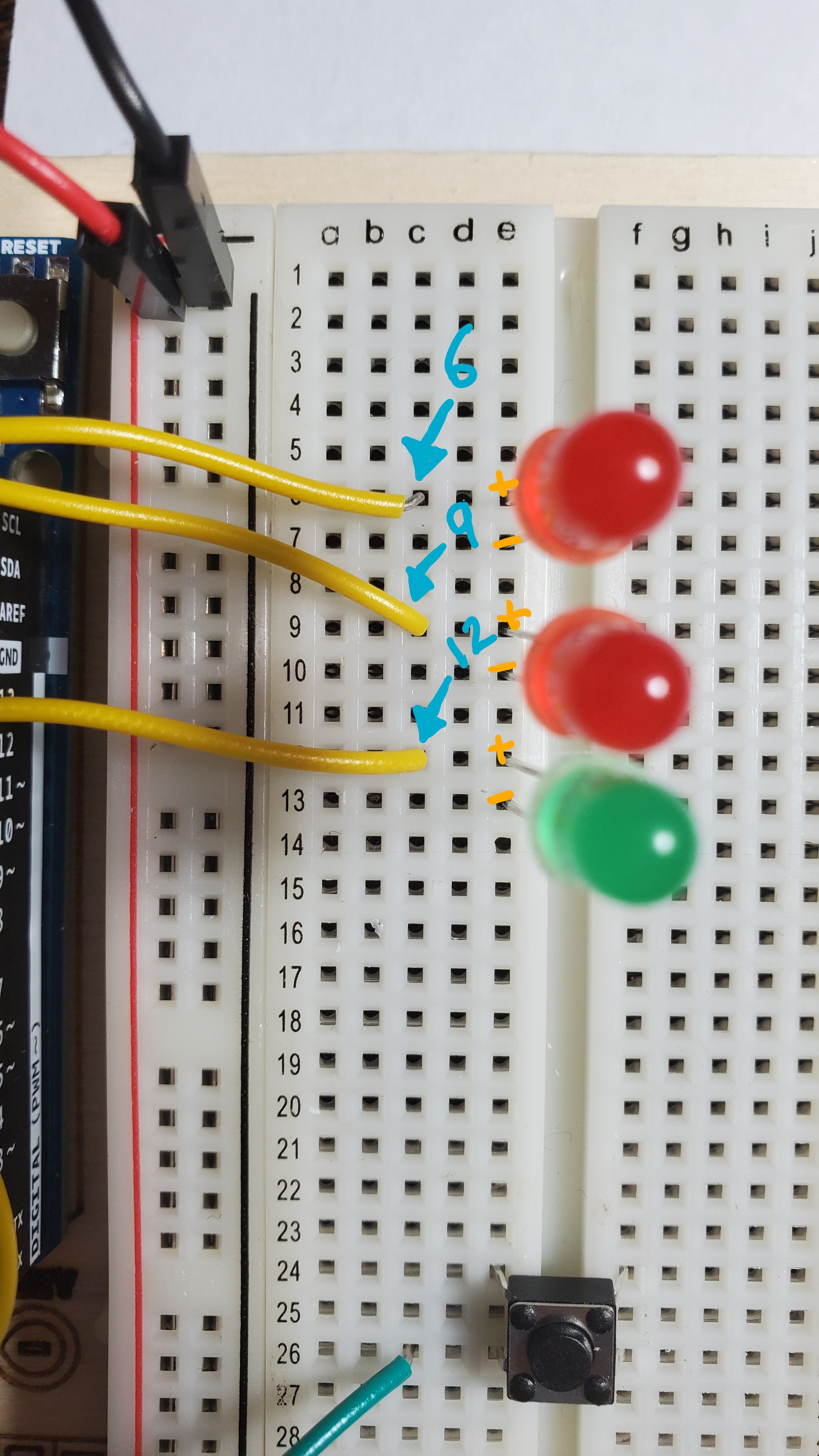
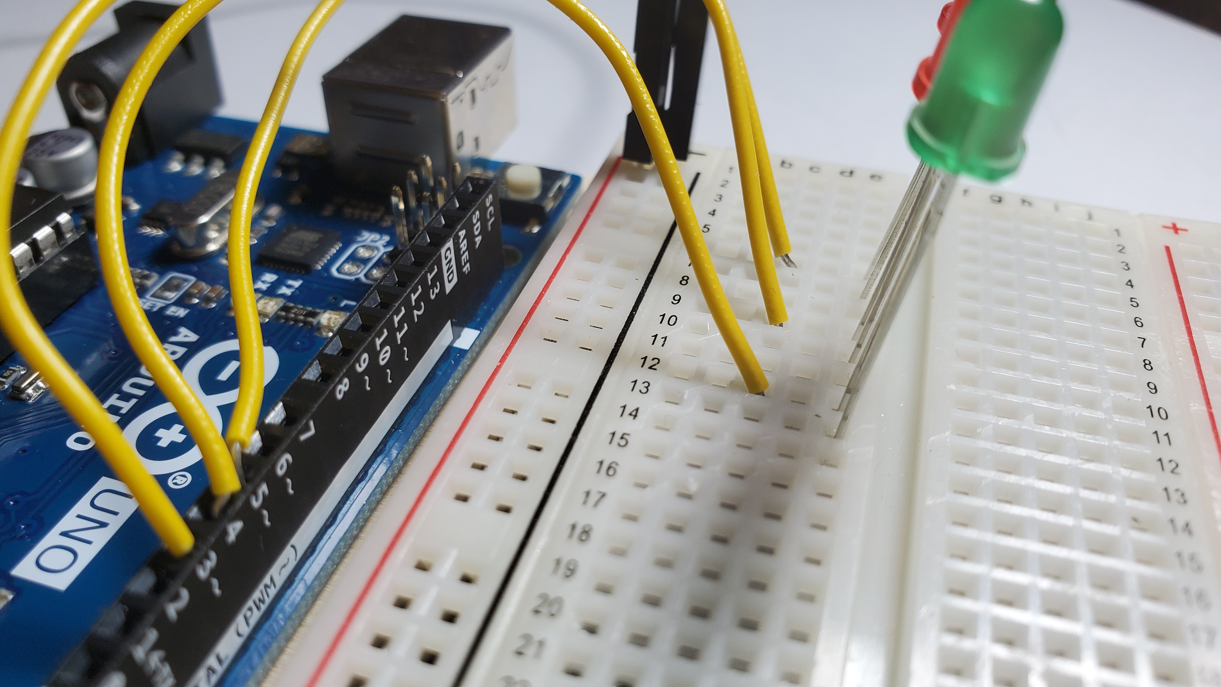
4) Pin yellow wires
Pin the yellow wires to the long leg of each LED
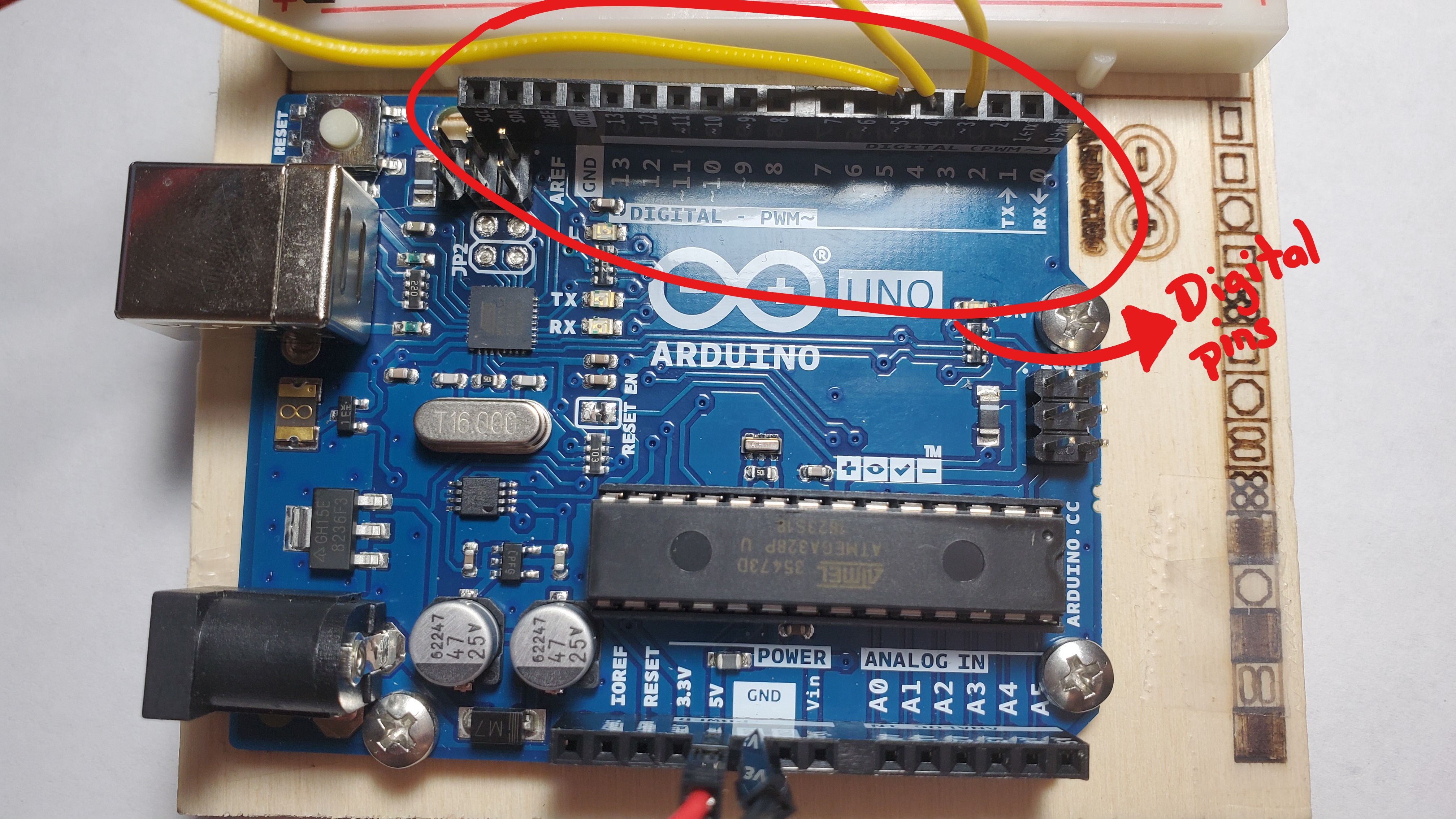
Pin a yellow wire from the Arduino digital pin ~3 row 12
Pin a yellow wire from the Arduino digital pin 4 to row 9
Pin a yellow wire from the Arduino digital pin ~5 to row 6
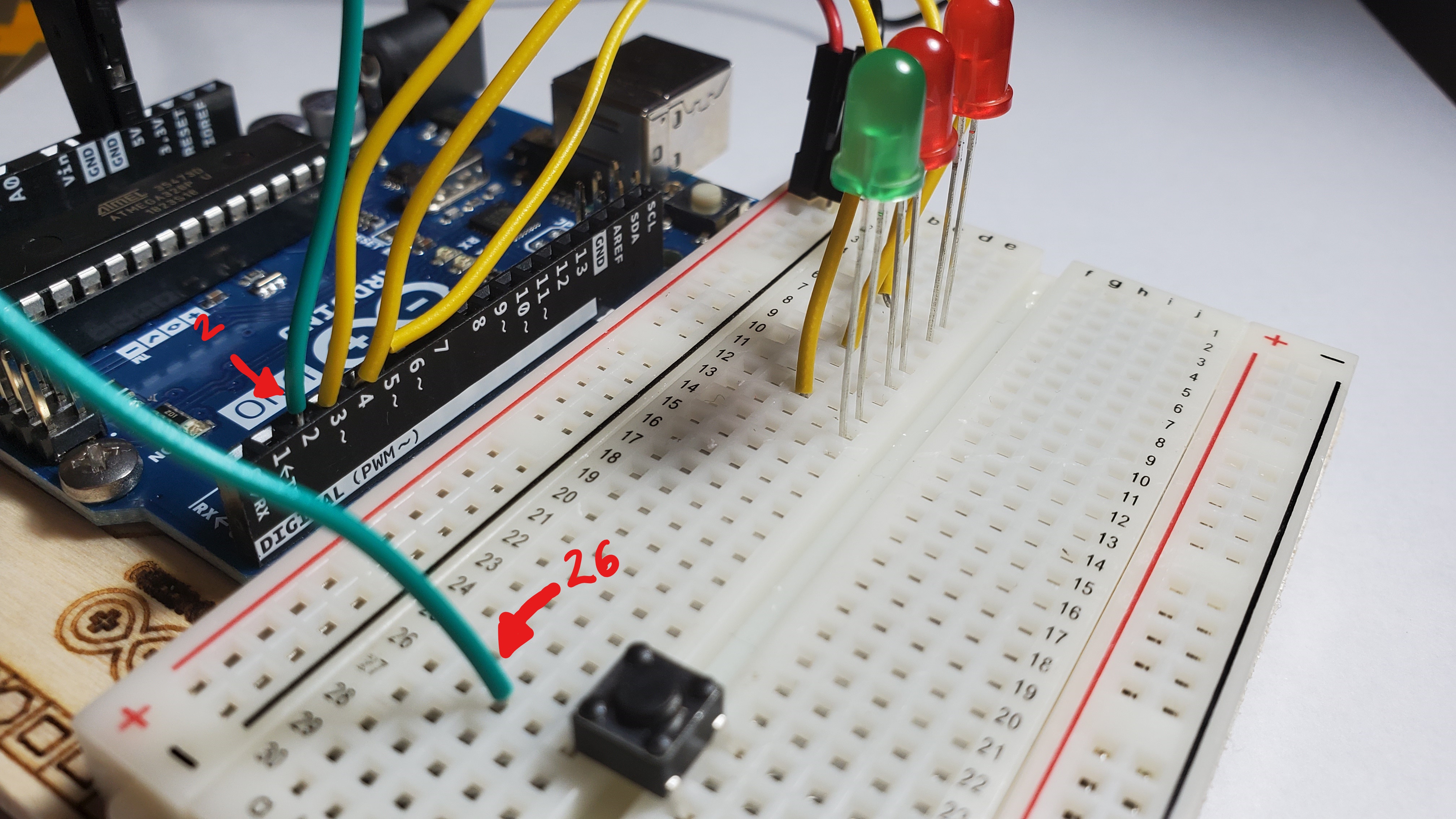
5)Pin the green wire
Pin the green wire from the Arduino digital pin 2 to row 26
6)Pin the 10 kilhom resitor to the button
Pin the resistor from the black side line to row 26. Right next to the green wire.
7)Pin the red wire
Pin red wire from the positive side line to row 24
8)Pin the three resistors to each LED
Pin one resistor from the negative side line to the short leg of the green LED (row 1)
Pin one resistor from the negative side line to the short leg of the red LED (row 10)
Pin one resistor from the negative side line to the short leg of the red LED (row 7)
9) Put the cardboard on top of the breadboard
Coding Instruction
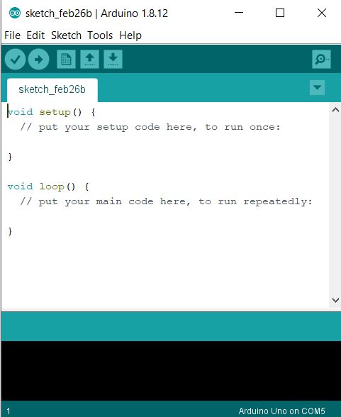
1) Open the Arduino IDE
Click on the Arduino logo that should be at the bottom of your screen
An Arduino IDE is where we write the code and then send it to the arduino board
IDE stands for Integrated Development Environment

2) Copy and Paste the following code on the IDE
Make sure to delete the default code in the IDE.
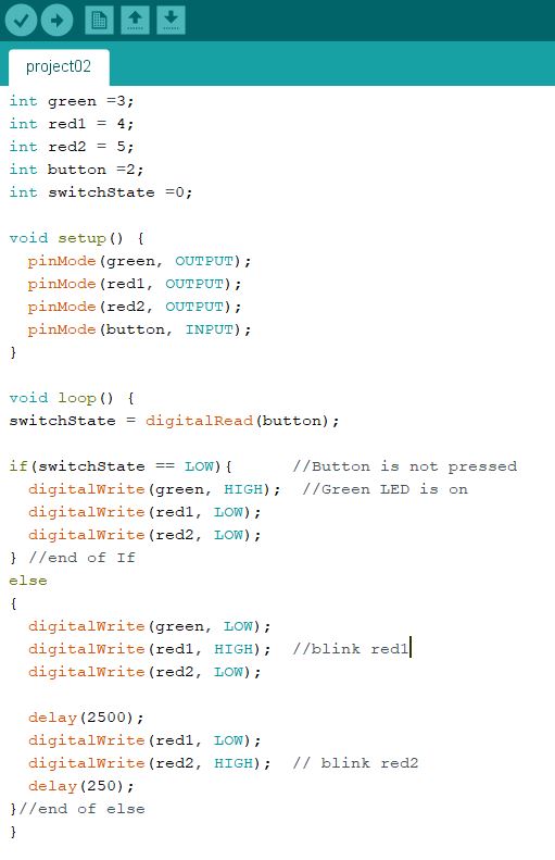
The Code
int green =3;
int red1 = 4;
int red2 = 5;
int button =2;
int switchState =0;

void setup() {
  pinMode(green, OUTPUT);
  pinMode(red1, OUTPUT);
  pinMode(red2, OUTPUT);
  pinMode(button, INPUT);
}

void loop() {
switchState = digitalRead(button);

if(switchState == LOW){      //Button is not pressed
  digitalWrite(green, HIGH);  //Green LED is on
  digitalWrite(red1, LOW);
  digitalWrite(red2, LOW);
} //end of If
else
{
  digitalWrite(green, LOW);
  digitalWrite(red1, HIGH);  //blink red1
  digitalWrite(red2, LOW);

  delay(2500);
  digitalWrite(red1, LOW);
  digitalWrite(red2, HIGH);  // blink red2
  delay(250);
}//end of else
}
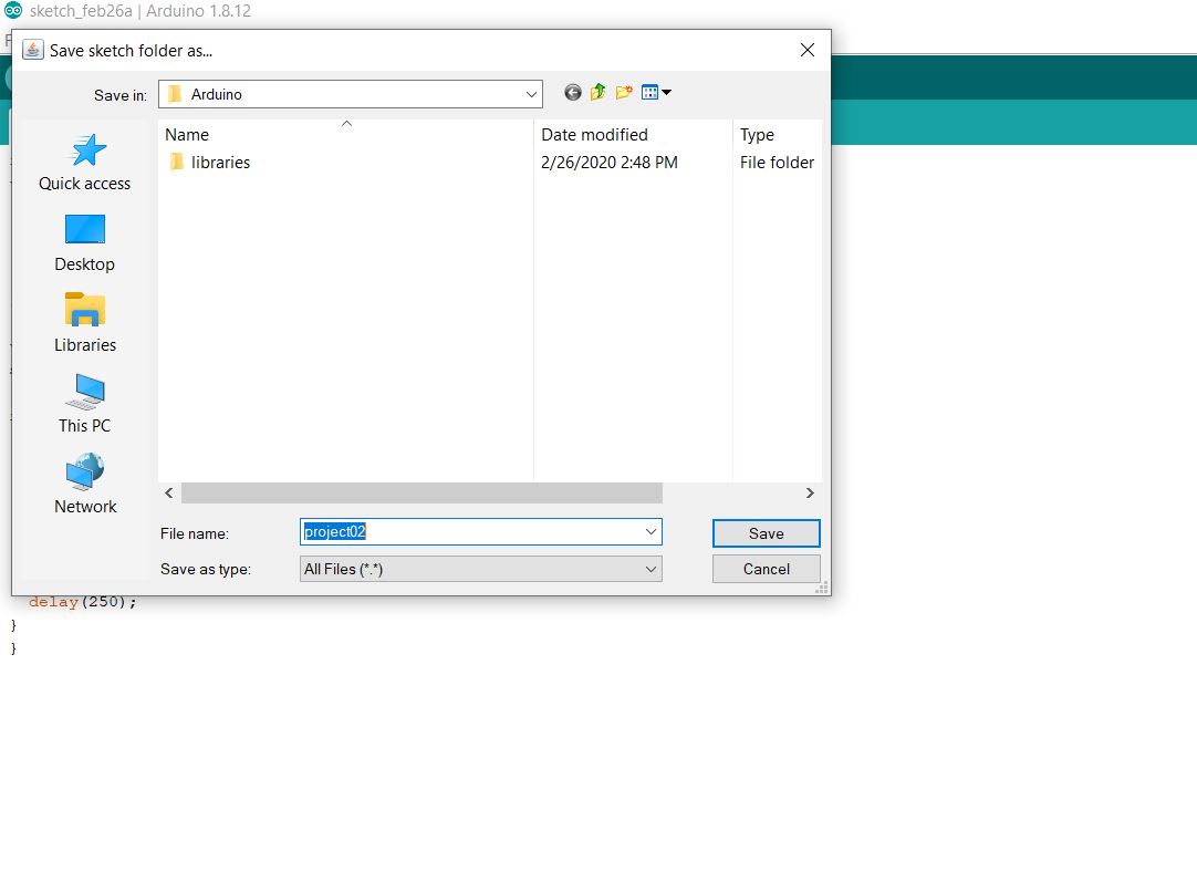
3) Save the code as Project02
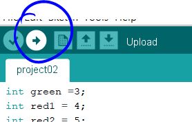
4)Upload the code to the arduino
Remmeber to plug in your arduino to the computer using the USB cable
Push the button
Push the button to see your code come to life
To reset the program, push the white button that is on the Arduino board next to the usb cable
